Improve your search results. Select your educational institution and subject so that we can show you the most relevant documents and help you in the best way possible.
Ok, I understand!
Your school or university
Improve your search results. Select your educational institution and subject so that we can show you the most relevant documents and help you in the best way possible.
ECET-105 Week 3 Lab Introduction to Digital Logic Gates (VERSION 2) With Latest Updated Solutions
Study guide • 9
pages
• 2020
ECET-105 Week 3 Lab Introduction to Digital Logic Gates
ECET-105 Week 3 Lab: Introduction to Digital Logic Gates
Objectives:
To understand basic logic functions (AND, OR, and NOT) and their complement used in Boolean algebra and digital logic design.
To test simple logic small-scale integration (SSI) integrated circuit (IC) devices.
Results: ► Conclusions: ► Observations/Measurements: ► Questions: ▼
Draw the schematic for a circuit that will function as indicated by the Boolean expres...
ECET-105 Week 3 Lab Introduction to Digital Logic Gates (VERSION 2) With Latest Updated Solutions
Last document update:
ago
ECET-105 Week 3 Lab Introduction to Digital Logic Gates
ECET-105 Week 3 Lab: Introduction to Digital Logic Gates
Objectives:
To understand basic logic functions (AND, OR, and NOT) and their complement used in Boolean algebra and digital logic design.
To test simple logic small-scale integration (SSI) integrated circuit (IC) devices.
Results: ► Conclusions: ► Observations/Measurements: ► Questions: ▼
Draw the schematic for a circuit that will function as indicated by the Boolean expres...
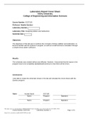
Draw a logic circuit that performs the following Boolean expression: Y=A∙((B+C)) ̅.
Determine the Boolean expression for the circuit shown below.
Write the Boolean expression for the logic circuit shown below.
Develop the truth table for the circuit shown in Problem 4.
Develop the truth table for the circuit shown below.
Develop the Boolean expression for the circuit shown in Problem 6.
Draw a logic circuit using only NAND gates to implement the following Boolean expression:...
ECET 105 DIGITAL FUNDAMENTALS WEEK 4 HOMEWORK ANSWER,GRADED A.
Last document update:
ago
Draw a logic circuit that performs the following Boolean expression: Y=A∙((B+C)) ̅.
Determine the Boolean expression for the circuit shown below.
Write the Boolean expression for the logic circuit shown below.
Develop the truth table for the circuit shown in Problem 4.
Develop the truth table for the circuit shown below.
Develop the Boolean expression for the circuit shown in Problem 6.
Draw a logic circuit using only NAND gates to implement the following Boolean expression:...
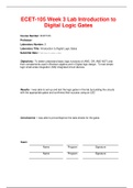
Does a typical computer have any analog outputs? If so, what are they?
List three advantages of digital signal representation as compared to their analog representation.
Convert 126 x 10+2 to scientific and engineering notations.
Make the following conversions:
a. Convert 0.34 seconds to milliseconds.
b. Express 0.0005 x 10⁻⁴ farads as picofarads.
The frequency of a signal is equal to the reciprocal of the signal’s period (f = 1/p).
The signal shown below is a sine wave as it might be d...
ECET 105 DIGITAL FUNDAMENTALS WEEK 1 HOMEWORK ANSWER
Last document update:
ago
Does a typical computer have any analog outputs? If so, what are they?
List three advantages of digital signal representation as compared to their analog representation.
Convert 126 x 10+2 to scientific and engineering notations.
Make the following conversions:
a. Convert 0.34 seconds to milliseconds.
b. Express 0.0005 x 10⁻⁴ farads as picofarads.
The frequency of a signal is equal to the reciprocal of the signal’s period (f = 1/p).
The signal shown below is a sine wave as it might be d...
Do you wonder why so many students wear nice clothes, have money to spare and enjoy tons of free time? Well, they sell on Stuvia! Imagine your study notes being downloaded a dozen times for $15 each. Every. Single. Day.
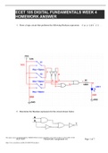
What is the duty cycle for a square wave signal that is HIGH for 15 nsec and LOW for 30 nsec?
2. A pulse train is shown on the oscilloscope below. Determine the period of the pulse.
3. Determine the frequency for a pulse that occurs every 10 ms.
4. What is the base-10 value for the binary number 11012?
5. What are the respective weights of the 1s in Problem 4?
6. How many different values can be represented by 6 bits, 7 bits, 8 bits, and 10 bits?
7. What is the minimum number of bi...
ECET105 Week 2 Homework Assignment,WELL EXPLAINED WITH VERIFIED ANSWERS.
Last document update:
ago
What is the duty cycle for a square wave signal that is HIGH for 15 nsec and LOW for 30 nsec?
2. A pulse train is shown on the oscilloscope below. Determine the period of the pulse.
3. Determine the frequency for a pulse that occurs every 10 ms.
4. What is the base-10 value for the binary number 11012?
5. What are the respective weights of the 1s in Problem 4?
6. How many different values can be represented by 6 bits, 7 bits, 8 bits, and 10 bits?
7. What is the minimum number of bi...
ECET 105 Week 7 Lab Flip-Flops and Enhanced Adder-Subtractor (VERSION 2) Latest Updated Version
Study guide • 13
pages
• 2020
ECET-105 Week 7 Lab: Flip-Flops and Enhanced Adder-Subtractor
I. OBJECTIVES
1. To test the operation of a 74LS74 D flip-flop and compare the operation with the predicted behavior
2. To test the operation of a 74LS112 J-K flip-flop and compare the operation with the predicted behavior
3. To measure propagation delays of a 74LS112 J-K flip-flop
4. To build and test an enhanced adder-subtractor
II. PARTS LIST
I. PROCEDURE
A. Test the 74LS74 D Flip-Flop
B. Test the74LS112 J-K Flip-Flop
C. Enhanced...
ECET 105 Week 7 Lab Flip-Flops and Enhanced Adder-Subtractor (VERSION 2) Latest Updated Version
Last document update:
ago
ECET-105 Week 7 Lab: Flip-Flops and Enhanced Adder-Subtractor
I. OBJECTIVES
1. To test the operation of a 74LS74 D flip-flop and compare the operation with the predicted behavior
2. To test the operation of a 74LS112 J-K flip-flop and compare the operation with the predicted behavior
3. To measure propagation delays of a 74LS112 J-K flip-flop
4. To build and test an enhanced adder-subtractor
II. PARTS LIST
I. PROCEDURE
A. Test the 74LS74 D Flip-Flop
B. Test the74LS112 J-K Flip-Flop
C. Enhanced...
ECET 105 Week 6 Homework Assignment # 6 latest August 2020 solution containing all questions and well explain answers DeVry University
Summary • 7
pages
• 2020
ECET 105 Week 6 Homework Assignment # 6
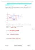
1. When a HIGH is on the output of the decoding circuit below, what is the binary code appearing on the inputs?
1. Write the Boolean equations for each of the following codes if an active-LOW decoder output is required. The first decode is shown as an example.
1. What are the active outputs of a BCD-to-7 segment decoder with an input of 0100?
1. A 7-segment decoder/driver drives the display below. Using the waveforms shown, determine the sequence of digits...
ECET 105 Week 6 Homework Assignment # 6 latest August 2020 solution containing all questions and well explain answers DeVry University
Last document update:
ago
ECET 105 Week 6 Homework Assignment # 6
1. When a HIGH is on the output of the decoding circuit below, what is the binary code appearing on the inputs?
1. Write the Boolean equations for each of the following codes if an active-LOW decoder output is required. The first decode is shown as an example.
1. What are the active outputs of a BCD-to-7 segment decoder with an input of 0100?
1. A 7-segment decoder/driver drives the display below. Using the waveforms shown, determine the sequence of digits...
Fear of missing out? Then don’t!
Do you wonder why so many students wear nice clothes, have money to spare and enjoy tons of free time? Well, they sell on Stuvia! Imagine your study notes being downloaded a dozen times for $15 each. Every. Single. Day.
Discover all about earning on Stuvia